
The battery is the core component of an electric vehicle, and its performance determines the technical indicators such as battery life, energy consumption, and service life of the electric vehicle. The battery tray in the battery module is the main component that performs the functions of carrying, protecting, and cooling. The modular battery pack is arranged in the battery tray, fixed on the chassis of the car through the battery tray, as shown in Figure 1. Since it is installed on the bottom of the vehicle body and the working environment is harsh, the battery tray needs to have the function of preventing stone impact and puncture to prevent the battery module from being damaged. The battery tray is an important safety structural part of electric vehicles. The following introduces the forming process and mold design of aluminum alloy battery trays for electric vehicles.
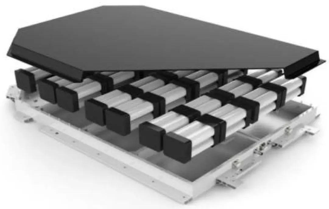
Figure 1 (Aluminum alloy battery tray)
1 Process analysis and mold design
1.1 Casting analysis
The aluminum alloy battery tray for electric vehicles is shown in Figure 2. The overall dimensions are 1106mm×1029mm×136mm, the basic wall thickness is 4mm, casting quality is about 15.5kg, and casting quality after processing is about 12.5kg. The material is A356-T6, tensile Strength ≥ 290MPa, yield strength ≥ 225MPa, elongation ≥ 6%, Brinell hardness ≥ 75~90HBS, need to meet air tightness and IP67&IP69K requirements.
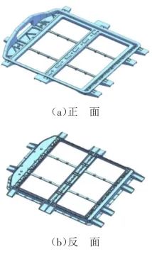
Figure 2 (Aluminum alloy battery tray)
1.2 Process analysis
Low pressure die casting is a special casting method between pressure casting and gravity casting. It not only has the advantages of using metal molds for both, but also has the characteristics of stable filling. Low pressure die casting has the advantages of low-speed filling from bottom to top, easy to control speed, small impact and splash of liquid aluminum, less oxide slag, high tissue density and high mechanical properties. Under low pressure die casting, the liquid aluminum is filled smoothly, and the casting solidifies and crystallizes under pressure, and the casting with high dense structure, high mechanical properties and beautiful appearance can be obtained, which is suitable for forming large thin-walled castings.
According to the mechanical properties required by the casting, the casting material is A356, which can meet the needs of customers after T6 treatment, but the pouring fluidity of this material generally requires reasonable control of the mold temperature to produce large and thin castings.
1.3 Pouring system
In view of the characteristics of large and thin castings, multiple gates need to be designed. At the same time, in order to ensure the smooth filling of liquid aluminum, filling channels are added at the window, which need to be removed by post-processing. Two process schemes of the pouring system were designed in the early stage, and each scheme was compared. As shown in Figure 3, scheme 1 arranges 9 gates and adds feeding channels at the window; scheme 2 arranges 6 gates pouring from the side of the casting to be formed. The CAE simulation analysis is shown in Figure 4 and Figure 5. Use the simulation results to optimize the mold structure, try to avoid the adverse impact of mold design on the quality of castings, reduce the probability of casting defects, and shorten the development cycle of castings.
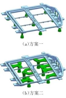
Figure 3 (Comparison of two process schemes for low pressure
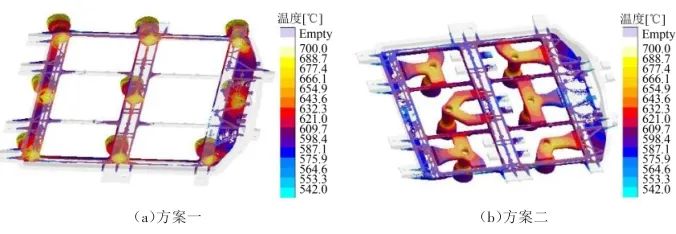
Figure 4 (Temperature field comparison during filling)
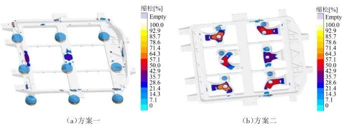
Figure 5 (Comparison of shrinkage porosity defects after solidification)
The simulation results of the above two schemes show that the liquid aluminum in the cavity moves upwards approximately in parallel, which is in line with the theory of parallel filling of the liquid aluminum as a whole, and the simulated shrinkage porosity parts of the casting are solved by strengthening cooling and other methods.
Advantages of the two schemes: Judging from the temperature of the liquid aluminum during the simulated filling, the temperature of the distal end of the casting formed by scheme 1 has higher uniformity than that of scheme 2, which is conducive to the filling of the cavity. The casting formed by scheme 2 does not have the gate residue like scheme 1. shrinkage porosity is better than that of scheme 1.
Disadvantages of the two schemes: Because the gate is arranged on the casting to be formed in the scheme 1, there will be a gate residue on the casting, which will increase about 0.7ka compared with the original casting. from the temperature of liquid aluminum in the scheme 2 simulated filling, the temperature of liquid aluminum at distal end is already low, and the simulation is under the ideal state of the mold temperature, so the flow capacity of the liquid aluminum may be insufficient in the actual state, and there will be a problem of difficulty in casting molding.
Combined with the analysis of various factors, scheme 2 was chosen as the pouring system. In view of the shortcomings of scheme 2, the pouring system and the heating system are optimized in the mold design. As shown in Figure 6, the overflow riser is added, which is beneficial to the filling of liquid aluminum and reduces or avoids the occurrence of defects in molded castings.
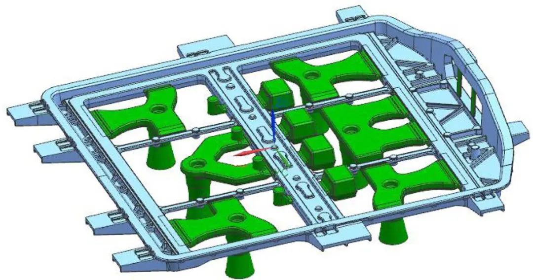
Figure 6 (Optimized pouring system)
1.4 Cooling system
The stress-bearing parts and areas with high mechanical performance requirements of castings need to be properly cooled or fed to avoid shrinkage porosity or thermal cracking. The basic wall thickness of the casting is 4mm, and the solidification will be affected by the heat dissipation of the mold itself. For its important parts, a cooling system is set up, as shown in Figure 7. After the filling is completed, pass water to cool, and the specific cooling time needs to be adjusted at the pouring site to ensure that the sequence of solidification is formed from the away from gate end to the gate end, and the gate and riser are solidified at the end to achieve the feed effect. The part with thicker wall thickness adopts the method of adding water cooling to the insert. This method has a better effect in the actual casting process and can avoid shrinkage porosity.
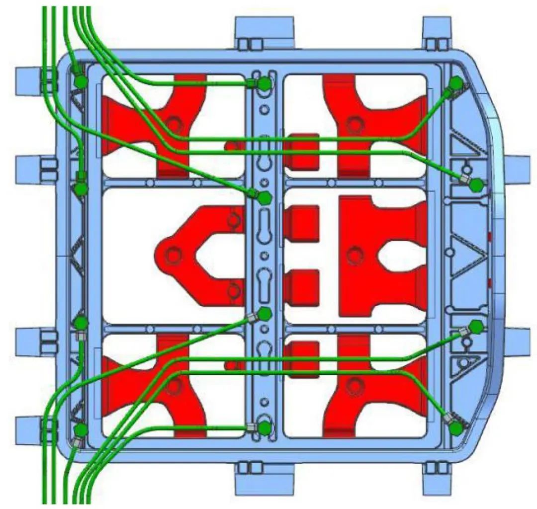
Figure 7 (Cooling system)
1.5 Exhaust system
Since the cavity of low pressure die casting metal is closed, it does not have good air permeability like sand molds, nor does it exhaust through risers in general gravity casting, the exhaust of the low-pressure casting cavity will affect the filling process of liquid aluminum and the quality of castings. The low pressure die casting mold can be exhausted through the gaps, exhaust grooves and exhaust plugs in the parting surface, push rod etc.
The exhaust size design in the exhaust system should be conducive to exhaust without overflowing, a reasonable exhaust system can prevent castings from defects such as insufficient filling, loose surface, and low strength. The final filling area of the liquid aluminum during the pouring process, such as the side rest and the riser of the upper mold, needs to be equipped with exhaust gas. In view of the fact that liquid aluminum easily flows into the gap of the exhaust plug in the actual process of low pressure die casting, which leads to the situation that the air plug is pulled out when the mold is opened, three methods are adopted after several attempts and improvements: Method 1 uses powder metallurgy sintered air plug, as shown in Figure 8(a), the disadvantage is that the manufacturing cost is high; Method 2 uses a seam-type exhaust plug with a gap of 0.1 mm, as shown in Figure 8(b), the disadvantage is that the exhaust seam is easily blocked after spraying paint; Method 3 uses a wire-cut exhaust plug, the gap is 0.15~0.2 mm, as shown in Figure 8(c). The disadvantages are low processing efficiency and high manufacturing cost. Different exhaust plugs need to be selected according to the actual area of the casting. Generally, the sintered and wire-cut vent plugs are used for the cavity of the casting, and the seam type is used for the sand core head.
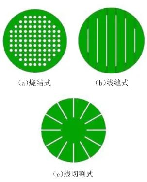
Figure 8 (3 types of exhaust plugs suitable for low pressure die casting)
1.6 Heating system
The casting is large in size and thin in wall thickness. In the mold flow analysis, the flow rate of the liquid aluminum at the end of the filling is insufficient. The reason is that the liquid aluminum is too long to flow, the temperature drops, and the liquid aluminum solidifies in advance and loses its flow ability, cold shut or insufficient pouring occurs, the riser of the upper die will not be able to achieve the effect of feeding. Based on these problems, without changing the wall thickness and shape of the casting, increase the temperature of the liquid aluminum and the mold temperature, improve the fluidity of the liquid aluminum, and solve the problem of cold shut or insufficient pouring. However, excessive liquid aluminum temperature and mold temperature will produce new thermal junctions or shrinkage porosity, resulting in excessive plane pinholes after casting processing. Therefore, it is necessary to select an appropriate liquid aluminum temperature and an appropriate mold temperature. According to experience, the temperature of the liquid aluminum is controlled at about 720℃, and the mold temperature is controlled at 320~350℃.
In view of the large volume, thin wall thickness and low height of the casting, a heating system is installed on the upper part of the mold. As shown in Figure 9, the direction of the flame faces the bottom and side of the mold to heat the bottom plane and side of the casting. According to the on-site pouring situation, adjust the heating time and flame, control the temperature of the upper mold part at 320~350 ℃, ensure the fluidity of the liquid aluminum within a reasonable range, and make the liquid aluminum fill the cavity and riser. In actual use, the heating system can effectively ensure the fluidity of the liquid aluminum.
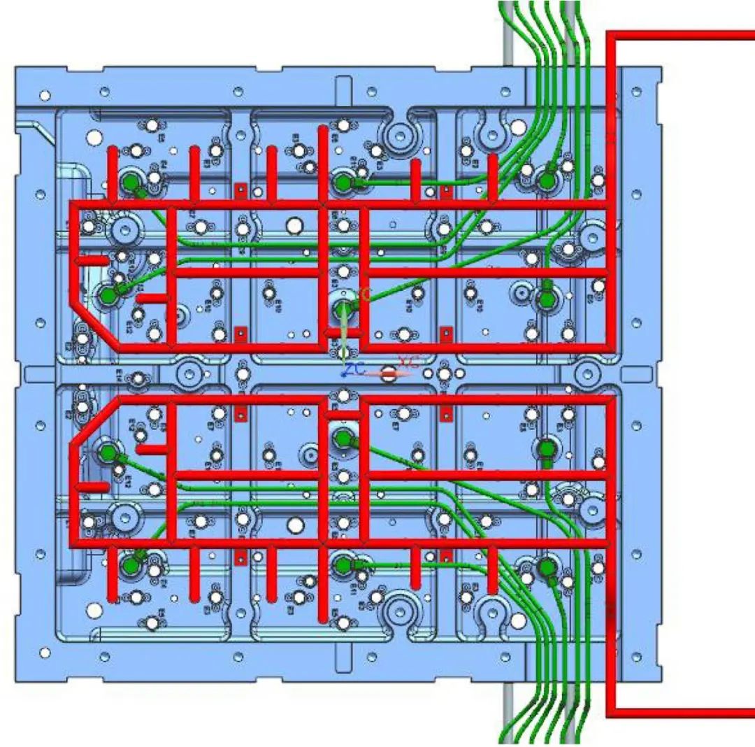
Figure 9 (Heating system)
2. Mold structure and working principle
According to the low pressure die casting process, combined with the characteristics of the casting and the structure of the equipment, in order to ensure that the formed casting stays in the upper mold, the front, rear, left and right core-pulling structures are designed on the upper mold. After the casting is formed and solidified, the upper and lower molds are opened first, and then pull the core in 4 directions, and finally the top plate of the upper mold pushes out the formed casting. The mold structure is shown in Figure 10.
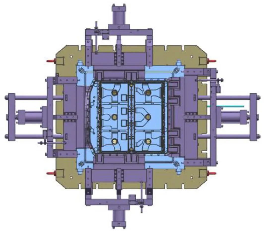
Figure 10 (Mold structure)
Edited by May Jiang from MAT Aluminum
Post time: May-11-2023


