
Recent advances in explainable Artificial Intelligence (AI) techniques have made it possible to extract useful and comprehensible information from predictive models. More specifically, post-hoc analysis techniques enable a unified approach to explain predictions made by any machine learning model. SHAP (SHapley Additive exPlanations) is one such tool, based on game theory, which extracts information about variable importance at both global and local levels (S. Lundberg, 2019).
The most common method for designing extrusion dies is the empirical design approach, with many formulas and design rules having been introduced and developed. Another widely adopted extrusion die design method is based primarily on engineering analogies and previous similar designs. The Finite Element Method (FEM) can be used for numerical simulation of the aluminum extrusion process; however, due to its high cost and complexity, the widespread application of such calculations in the extrusion industry is limited. In porthole die extrusion processes, serious flow problems mainly arise from errors in the porthole dimensions (area, position, etc.), which can lead to significant profile deflection, substantial lateral core deflection, and changes in profile thickness.
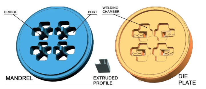
To achieve effective porthole die design, it is essential to ensure: mechanical strength of all components, and uniform exit velocity of the extruded profile section throughout the forming process.
On the other hand, to achieve uniform exit velocity of the extruded profile, the main variables required in the design include: balancing the port geometry to ensure uniform aluminum velocity within the die welding chamber; and optimizing the bearing dimensions based on the profile thickness and its position within the die.
These are the primary factors, but it should be noted that there are other secondary factors and decisions in the design process that also affect flow balance: section layout, bridge shape, etc.
The most common design criterion is balancing the concentric velocity difference of the aluminum billet by appropriately positioning and sizing the portholes. Therefore, the aluminum flow must be able to achieve average velocity and pressure across all ports, from entry at the die front into the ports to entering the welding chamber. Once a balanced design for all ports is achieved through this criterion, the definition of the bearing in the profile geometry becomes simple, as it primarily depends on the profile thickness.
Porthole size issues mainly arise in multi-cavity dies, where multiple ports are located at very different distances from the die center. The concentric velocity distribution at the die front means that the porthole dimensions must be determined based on the ratio of their area to perimeter relative to their distance from the die center.
The variables for porthole design are as follows: Port Area – Determines the amount of aluminum entering that die region. Port Perimeter – Determines the friction generated between the die and the aluminum flux passing through the port. Distance from Center to Port Center – Determines the aluminum velocity at the port entrance face. Due to the concentric velocity distribution inside the billet, the exact position of the port is not critical, but its distance from the center is. Ports with the same area positioned symmetrically about the die center will perform identically during extrusion.
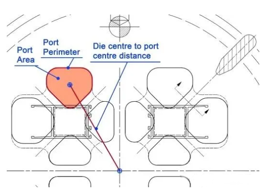
These variables geometrically define the port of the die.
The following variables are considered for the extruded profile section affected by each port: Area of the extruded profile section affected by the corresponding port – Determines the ease with which aluminum flows in that die region. Thus, it also regulates the amount of aluminum at the inlet port to ensure flow balance. Perimeter of the extruded profile section affected by the corresponding port – Determines the profile’s constraining capacity for free aluminum flow in that section. Hence, it also regulates the amount of aluminum at the inlet port to achieve flow balance. Distance between the porthole center and the center of the affected extruded profile area – Quantifies the directness of exposure of that profile to the incoming aluminum flux.
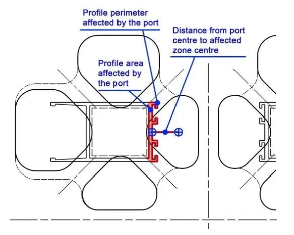
Variables used to consider the effect of each port on the extruded profile section.
Therefore, these global variables allow the integration into the model of the question of whether to use primary or secondary ports in the design. These global variables include: Total area of the entire port set – Determines the total amount of aluminum flowing into the die. Total perimeter of the entire port set – Determines the overall frictional resistance of the die to aluminum flow.
Application of the Machine Learning-Based Model
The different steps for applying the new machine learning model to the example case are as follows:
First, starting from the geometric profile requiring die production, a set of ports is designed based on the profile geometry and design criteria dictated by designer experience (the machine learning-based model is not involved in this stage).
Then, the geometric data of the newly designed port set is collected and input into the machine learning-based model.
The machine learning-based model displays the correct port area values, which are compared with the initial design area values for each designed port.
Based on the quantile in which the RMSE falls, a decision is made regarding the suitability of the port design according to the criteria provided in Section 3.4.
If the RMSE falls within the Q3 quantile range, the design requires revision; if it is above the Q3 quantile, the design must be revised.
To make these modifications, it is recommended to rely on the interpretability of the model to help determine the most appropriate direction and method, enabling us to approach the values that best fit the model variables.
After making the corresponding changes, the machine learning-based model reevaluates all ports (if any port changes, the model values for the remaining ports will also change because the total area variable participates in the model). If the RMSE value for any port is still outside the desired range, steps 5 to 7 must be repeated until all ports are within the required range.
When the geometry needs to be adjusted to properly fit the machine learning-based model, one of the two most controllable geometric variables is typically used: Port Area or Distance. Modifying the port area is usually easier because altering the profile position is difficult due to other design conditions. Therefore, it can be said that the most effective way to change the geometric characteristics of a port is to modify the area of the port farthest from the profile.
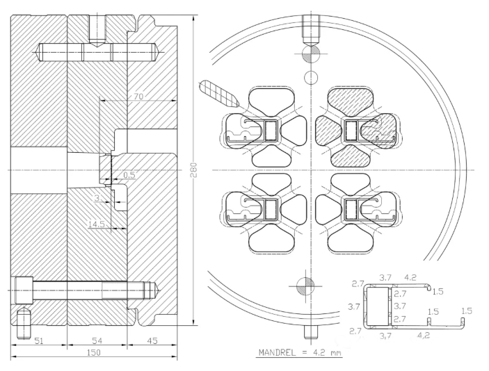
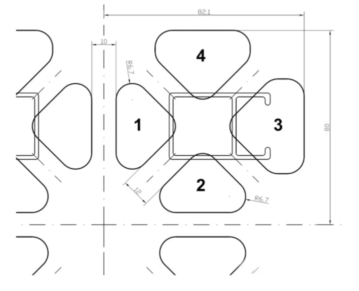
The picture below shows the profile required for a press with a 203 mm container and a force of 22000 MN, requiring a four-cavity, four-hole design. The designer must use this data to begin designing the die. The example focuses on the design of the mandrel ports, for which the machine learning-based model has been developed, although die design includes other steps.
The designer must first position the profile cavities relative to the die center, considering support constraints. For layout, the most common choice for this type of profile is a symmetrical arrangement and orientation of the profiles, supported on the face, which provides greater stability. Subsequently, a first attempt is made to design the ports, considering the profile positions and a minimum width between ports of 10–13 mm (minimum distance between ports).
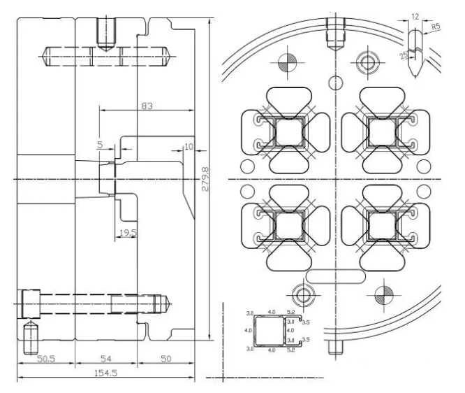
Based on these design criteria, an initial design attempt is made. It adopts a vertically and horizontally symmetrical design, with bridges 12 mm wide and a central wall 10 mm wide.
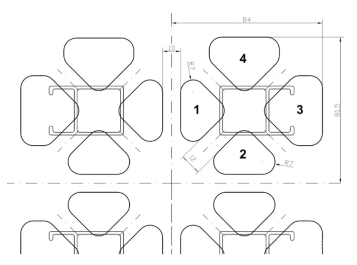
Initial four-cavity design.
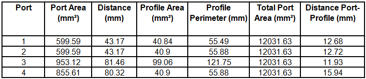
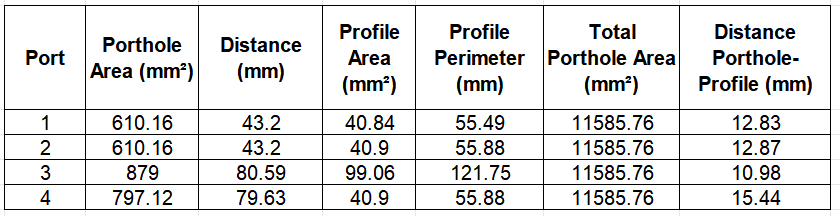
For these initial geometries, the variable values for the machine learning-based model were used as input to obtain the model predictions, along with the associated error and its corresponding quantile.
Values of the initial design variables for the example die
Machine learning-based model predictions for the initial design ports and the contributions of each variable.
Analysis and recommendations provided by the machine learning-based model for the initial design ports
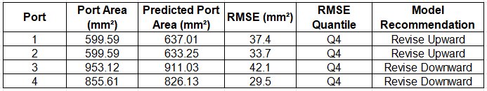
Therefore, ports numbered 1 and 2 must be increased in area to better fit the model. Additionally, the areas of ports 3 and 4 must be reduced to better fit the model. As changes in the inlet area also involve other variables, it is difficult to accurately estimate the extent to which the inlet area should be adjusted; hence, iterative approximation must be performed in the direction indicated by the model.
At this point, model interpretability comes into play, as it helps the designer make optimal decisions, minimizing the number of iterations required to fit the target Port Area values.
To increase the area of Ports 1 and 2, their geometry must be changed. The most common and simplest method is to perform all port modifications, if possible, without changing the bridge positions. If the port geometry is modified in this way, only the variable values for Total Port Area, Distance, and Distance Port-Profile will be altered.
Total Inlet contributes positively to the inlet values for Portholes 1 and 2, while Distance and Distance Inlet-Profile contribute negatively.
However, this is not the case for the variables Distance and Distance Port-Profile. Changes in these variables can make achieving the final goal easier or harder, depending on the increase in Port Area. If a decision is made to increase Port Area by reducing the central wall by 10 mm, the values of Distance and Distance Port-Profile (especially the latter) will increase, and the resulting negative contribution will lower the Port Area value targeted by the model (which is entirely contrary to the goal of increasing Port Area).
For Portholes 1 and 2, it was decided to increase the porthole area solely by reducing the fillet radius, meaning the increase in porthole area hardly changes Distance and Distance Port-Profile.
Conversely, the area of Portholes 3 and 4 must be reduced. For these portholes, the contributions of Distance and Total Porthole Area are positive, while the contribution of Distance Porthole-Profile is negative. Therefore, it was decided to modify the area by stretching the geometry and reducing the porthole area, Total Porthole Area, and Distance. The contributions of Total Porthole Area and Distance align with the direction of the modification made. In this case, Distance Port-Profile also decreases, slightly contributing in the opposite direction to the intended modification.
The interpretability of the model and a simple two-step iterative process helped us define a new geometry for the ports in the example die, perfectly fitting the machine learning-based model.
Improved four-cavity design for this example, based on machine learning-based model indications.
For these improved geometries, the variable values for the machine learning-based model were used as input to obtain the corresponding model predictions and error metrics.
Variable values used for the improved example die design
Machine learning-based model predictions for the ports in the improved design, including variable contributions.
Analysis and recommendations provided by the machine learning-based model for the improved port design
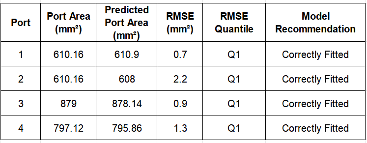
Thus, this new design allows all ports to fit appropriately into the machine learning-based model; therefore, this port design can be considered adequate.
Once the optimal port design is achieved, the remaining elements must be defined to complete the design. The choices made during definition must follow standard criteria to ensure that the calculated balanced ports are reflected in the balanced flow of aluminum during extrusion. The defined design factors and criteria used are as follows:
Bridges possess the following geometric characteristics: width of 12 mm. For a profile of this size, bridge width is typically between 12 and 14 mm; this value was chosen to create wider ports (more sensitive to flow imbalance). Welding angle of 25 degrees. The welding angle is usually between 20 and 30 degrees. An intermediate value was chosen, which is more favorable for welding without excessively long weld distances (Valberg, 2002).
The welding chamber depth was defined as 14.5 mm, equipped with 4×5 mm feeders (typically used for adjustments within die life). Considering the chosen bridge width, this weld height is considered high (Donati and Tomesani, 2005). This allows welding to proceed without restriction (Selvaggio et al., 2011; Ceretti et al., 2009).
The bearing length was defined solely based on thickness (constant here) and reduced at the apex (Miles et al., 1997) and below the bridges (Xue et al., 2018).
Finally, the component height was determined based on strength calculations to ensure durability under pressure and temperature cycling conditions.
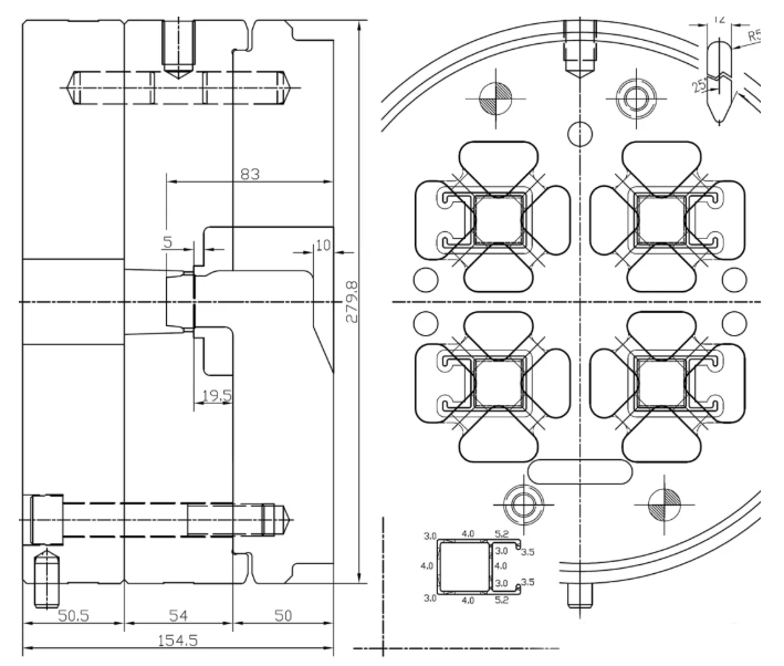
Final die design
Post time: Jun-12-2026


