
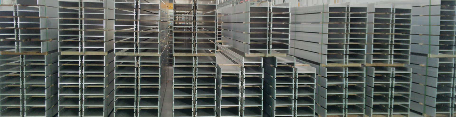
Tool durability is a function of many parameters, including the mechanical and physical properties of the tool material, the nature and parameters of the forming process, and the properties of the material to be formed. In aluminum extrusion, dies are subjected to complex stress conditions and high temperatures; therefore, the performance of the die material plays a crucial role in ensuring the durability of a given tool. Currently, H-13 tool steel is used as the die material for aluminum extrusion. In most cases, two factors limit the service life of dies: severe wear in the bearing channel area and fracture in stress concentration areas, a mechanism related to cyclic softening. While surface hardening techniques can be applied to prevent wear on the bearing surface, materials with higher fatigue resistance should be used to avoid fatigue cracking. In this regard, superalloys are being considered as candidate die materials for aluminum extrusion. For instance, it is well known that Nimonic alloy PK 37, produced by Norsk Specialmetall AS, has been successfully used as a material for copper and aluminum bronze extrusion die inserts, thereby extending tool life. The advantage of superalloys over currently used tool steels stems from their higher yield strength, toughness, and hardness at operating temperatures (500–600°C), which increases the time to fatigue crack initiation. However, the wear resistance of nickel-based superalloys during aluminum extrusion is not well documented. Conversely, the wear mechanisms for steel dies are fairly well understood. It is a combination of two modes: adhesion and abrasion. Due to the strong tendency of aluminum to adhere to steel surfaces, it forms an adhesive layer on the die bearing surface. The development of this adhesive layer is directly related to the normal pressure generated in the bearing channel. This layer typically has three constituents that alternate along the bearing surface as pressure levels change. At the bearing entrance, where pressure is very high, the oxide layer that always covers the steel surface is quickly removed by the flowing aluminum and cannot reform due to lack of oxygen. As a result, interaction is established between nascent aluminum (as it comes from within the billet) and nascent steel, leading to a very high coefficient of friction and a change in friction conditions from sliding to sticking. In this sticking zone, a very thin, spotty aluminum deposit fills the valleys of the steel surface. Pressure decreases significantly towards the bearing exit, preventing the flowing aluminum from smearing into the deepest recesses of the tool surface and allowing oxygen to penetrate channels not occupied by aluminum, thus maintaining a stable oxide layer. The presence of such a layer between the workpiece and tool results in a significant drop in the friction coefficient. Consequently, a sliding zone forms near the bearing exit, where a very thick (1-10 µm) adhesive layer, also containing magnesium, aluminum, iron, and silicon, develops alongside oxygen. A transition zone, exhibiting mixed stick-slip characteristics, is located between the sticking zone and the sliding zone.
At the entrance of the bearing channel, strong chemical bonding leads to a sticking condition, preventing aluminum flow. Near the exit, the thick adhesive layer acts as a diffusion barrier, preventing wear caused by chemical reactions. Thus, no significant wear occurs in the sticking and sliding zones. Conversely, conditions for chemical reaction are optimal in the transition zone, where there is sufficient aluminum flow without a diffusion barrier. Due to the low oxygen concentration in this zone, reactions occur on nascent surfaces, leading to the formation of intermetallic compounds. The production of these compounds can give rise to two wear mechanisms: continuous dissolution of the tool material and fracturing of the tool material, as the flow resistance of the newly formed compound may often be higher than that of the bulk material. The presence of these zones, their widths, and locations depend on factors such as temperature, die geometry, and extrusion speed. Furthermore, hard Al₂O₃ particles detached from the extrudate, as well as alumina, have been found embedded in the adhesive layer. By occupying different regimes within the bearing channel, particles can be removed from the adhesive layer or move within it, preferably in the sticking zone, thereby causing abrasion.
The Inconel 718 die was homogenized at 1050°C for 1 hour and annealed at 760°C and 650°C for 10 hours, resulting in a hardness of 45 HRC and a yield strength (Rp0.2) of 980 MPa. The die was not subjected to any surface treatment. The chemical composition of the material was examined using a JEOL JXA-8900M electron probe microanalyzer and is listed alongside the nominal composition provided by the supplier in Table 1. In this case, the alloy’s microstructure consists of a nickel matrix in which γ‘ and γ” phases are precipitated. Dissolved cobalt, chromium, molybdenum, tungsten, and titanium atoms promote precipitation. γ” (Ni₃Nb) is the primary strengthening phase, precipitating as very dense, coherent disc-shaped particles with a diameter of approximately 60 nm and a thickness of about 5-9 nm. Its strengthening effect is mainly due to large coherency strains, and its moderate hardness (~45 HRC) prevents severe embrittlement of the material, unlike strengthening from harder phases such as carbides. A small amount of the γ‘ phase (Ni₃(Al, Ti)) is also present in the microstructure, but its effect is minimal. Among the carbide phases, chromium-rich M₂₃C₆ carbides predominate. They are found primarily along grain boundaries, typically as irregular, discontinuous, rounded, or blocky particles about 20-50 nm in size.
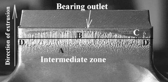
Figure 1. Die mandrel containing wear pattern. Line DD indicates the initial position of the bearing entrance.
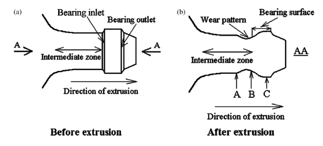
Figure 2. (a) Sketch of the die mandrel with the bearing surface. (b) Sketch of a longitudinal section of the mandrel through the excessive wear. The section of the worn mandrel is taken through section plane AA, as shown in (a).
Figure 1 shows one side of the die mandrel where excessive wear occurred. Similar wear patterns were observed on the other three sides of the mandrel. The wear pattern consists of two distinct wear regions. The die was severely worn in the area near the bearing entrance, with the entrance being leveled down to the level of the middle region between the welding channel and the bearing surface (Figure 2). This is region B in Figures 1 and 2b. Here, the topography consists of deep grooves forming a focal point, extending 8-9 mm long and tending towards the middle zone. The grooves are approximately 100-150 µm wide, with a maximum depth of 150-200 µm occurring 8-10 mm from the exit, i.e., in the middle region. Consequently, substantial material loss occurred. Beyond this severely worn area, the mandrel suffered only minor wear in the region denoted as A. Here, the wear has a pimple-like topography. Initially, it was hypothesized that the pimple-like irregularities might be due to hard particles (much harder than the matrix) still located beneath the “pimples”. There are no inclusions beneath the “pimples,” nor is there evidence that they were present and fell out when the specimen was sectioned. Finally, no wear occurred at all in the area close to the bearing exit. The width of this region varies from 1 to 4 mm. Surface roughness measurements of regions A, B, and C quantitatively confirm the differences in wear severity between the zones.
The greatest material removal occurred at a distance of 8-10 mm from the bearing exit, in the area beyond the initial bearing surface, but the bearing entrance was also severely worn. The pimple-like topography in Zone A likely represents an early stage of wear, which might also occur near the bearing entrance (Zone B) after the first extrusion cycles. With increasing number of cycles, the pimple-like morphology develops into the wear grooves observed in Zone B after 40 cycles. In conventional terms, this process led to incremental material removal. After the bearing entrance was destroyed, the area of the bearing surface increased considerably, i.e., the middle region began to contact the aluminum. Thus, the final wear pattern may represent, proportionally, the condition of the original bearing surface during the intermediate stage of wear, i.e., the stage before the bearing entrance was destroyed.
The application of Inconel 718 alloy as a tool material for hot aluminum extrusion proved beneficial. Die life was extended to 40 cycles without the initiation of fatigue fracture, whereas the life of H-13 steel dies, limited by fatigue failure, is approximately 30 cycles.
• The wear mechanism for Inconel 718 aluminum extrusion dies is similar to that for steel dies. Maximum material damage occurred in the middle of the contact interface, while the area in front of the middle section and the area near the bearing exit experienced minor wear and no wear, respectively.
• The findings suggest that an interfacial chemical reaction occurred between the die material and the extrudate, producing intermetallic compounds.
• Under the influence of high tensile stress, tearing of the die material due to strong chemical bonding between the die and extrudate contributes to die wear.
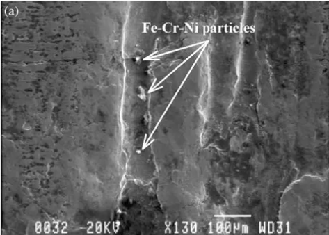
• Detached intermetallic compounds, as well as aluminum and aluminum-silicon oxides, act as abrasive particles, contributing to die wear.
Post time: Mar-20-2026


