
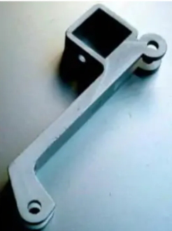
We have tried to collect detailed information regarding surface defects in aluminum extrusions. These are extruded profiles made of soft and medium strength aluminum alloys such as 6060, 6063, 6005A, 6061 and 6082. High strength aluminum alloy profiles (e.g., 2xxx, 5xxx and 7xxx series alloys) may also have their own types of defects due to their high alloy content and specific manufacturing techniques.
1.1 Pick-up
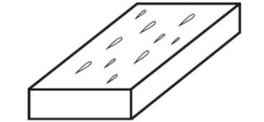
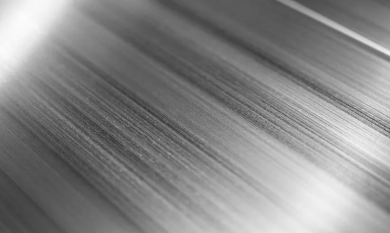
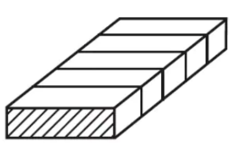
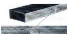
Small particles of aluminum and aluminum oxide are torn from the surface of the profile and later redeposited on the surface. They have a comma or comet-like morphology, pointing in the extrusion direction. May be related to “die lines” defects.
Comma-shaped spots torn on the extruded product surface, caused by local material deposits on the die surface.
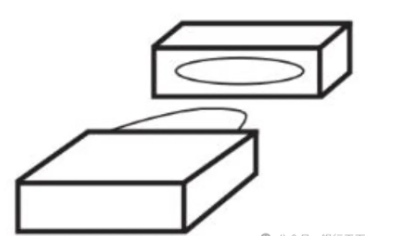
Schematic diagram of “Pick-up” defect
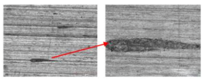
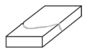
“Comet tail” appearance of “Pick-up” defect
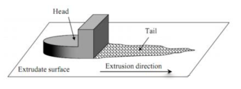
Model of “Pick-up” defect
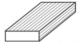
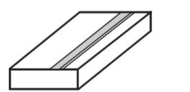
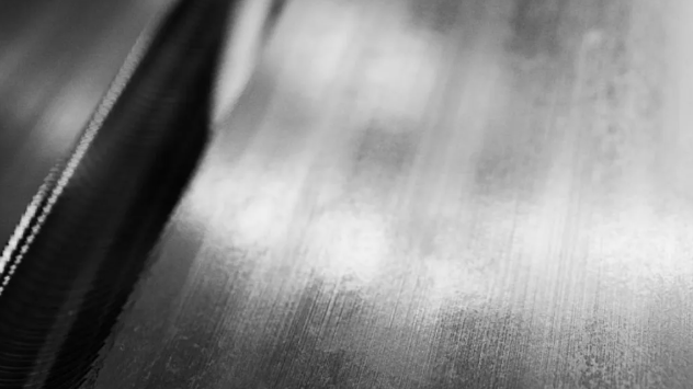
1.2 Die Lines
Grooves extending in the extrusion direction, usually terminating at points where material particles are attached. May be related to “Pick-up” defects.
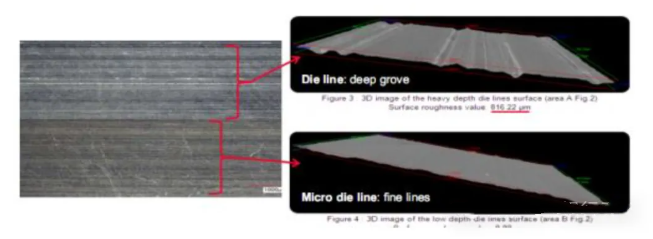
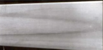
Continuous longitudinal lines formed on the extruded product caused by minor irregularities and/or accumulation of aluminum or non-metallic inclusions on the die bearing surface.
Micro Die Lines. Even with optimal die bearing lengths and extrusion temperatures, combined with highly polished die bearings, die lines can still appear. These die lines are finer and shallower, referred to as micro die lines.
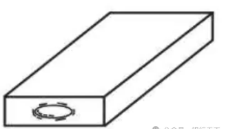
Schematic diagram of “Die Line” defect
Die lines and micro die lines
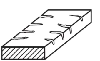
1.3 Die Streaks
Light or dark streaks along the extrusion direction. Usually caused by overly abrupt changes in die bearing length.
Longitudinal discoloration, usually lighter than the surrounding metal, which may be due to uneven cooling, i.e., large variations in wall thickness. Wide streaks are often referred to as “Stretchers”.
Schematic diagram of “Die-related Streaks” defect
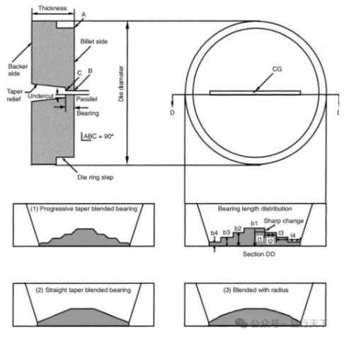
Bearing length changes at points of confluence must be appropriately blended to prevent streaking
1.4 Dark Streaks
Streaks extending in the extrusion direction in areas of profile cross-section changes (e.g., sections, hollow chambers, etc.). They exhibit convex-concave protrusions, or different reflections on the profile surface due to structural differences.
Schematic diagram of “Dark Streak” defect
Dark Streaks
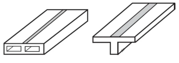
1.5 Longitudinal Extrusion Seeming Streaky (Has Lines, Welds)
Fine streaks extending in the extrusion direction, appearing lighter or darker than the rest of the material depending on lighting conditions. Longitudinal weld lines are process-related and unavoidable, but their extent can be influenced.
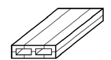
Schematic diagram of “Longitudinal Extrusion Seeming Streaky” defect
Longitudinal extrusion on a 6063 profile
1.6 Front End Defect (Transverse Weld Defect)
Parabolic-shaped defect. This is caused by poor welding during the billet-to-billet extrusion process when welding two billets, due to trapped oxides and lubricant from the billet end surfaces.
Schematic diagram of “Transverse Weld” defect
Transverse welding
1.7 Back End Defect
A cone-shaped defect caused by contamination and oxides accumulating ahead of the advancing extrusion pad, and liner friction leading to ring-shaped separation at the rear of the extrusion.
Schematic diagram of “Back End” defect
Back end defect
1.7 Speed Cracks (Speed Tearing)
Cracks on the surface, mostly transverse to the extrusion direction, at a 45-degree angle at the strand edges, appearing as openings in extreme cases.
Transverse cracks, preferentially occurring at corner radii or ends of the profile, caused by locally high temperatures.
Schematic diagram of “Speed Crack” defect
Speed cracks
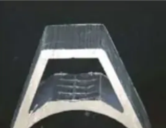
1.8 Blisters
Bubbles of different sizes arranged in lines or irregular patterns, aligned along the extrusion direction.
Raised points on the product surface with underlying depressions, formed when air penetrates into the subsurface region. Cavities resulting from burst blisters are often called “pinholes”.
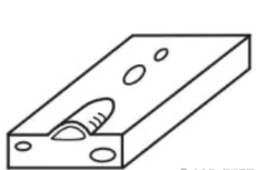
Schematic diagram of “Blisters” defect
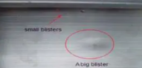
One large blister and one small blister
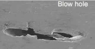
A pinhole
1.9 Surface Waviness
Surface waves may appear over short distances along the entire length of the profile. The defect may appear on the entire strand surface or on one or more partial surfaces. Often occurs in easily extrudable alloys.
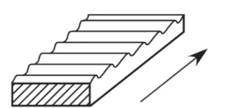
Schematic diagram of “Surface Waviness” defect
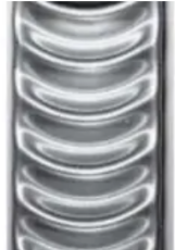
Surface waviness

Waviness caused by incorrect metal flow in the die
1.10 Chatter Marks
Marks on the profile surface repeating at roughly equal distances. This defect is common in low-alloy extrusion alloys with very high extrusion ratios.
Uniformly distributed surface marks, transverse to the extrusion direction, formed by vibration between the metal and the working surface during the manufacturing process.
Schematic diagram of “Chatter Mark” defect
1.11 Stop Mark
Circular rings perpendicular to the extrusion direction (located in the transverse extrusion seam area) for billet-to-billet extrusion.
Schematic diagram of “Stop Mark” defect
Stop marks
1.12 Snap Mark (Stop Mark)
Rings with varying cutting holes can appear at any point on the strand.
A band-like pattern around the extrusion cross-section, perpendicular to its length. It is caused by sudden changes in extrusion parameters during the process. If the extrusion process is abruptly interrupted, the term “stop mark” is used.
Schematic diagram of “Snap (Stop) Mark” defect
“Stop Mark” defect
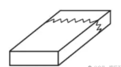
1.13 Broken Die
Cross-section deviating from the target section due to missing parts of the extrusion die or misaligned sections of complex extrusion dies.
Schematic diagram of “Broken Die” defect
Post time: Mar-11-2026


