
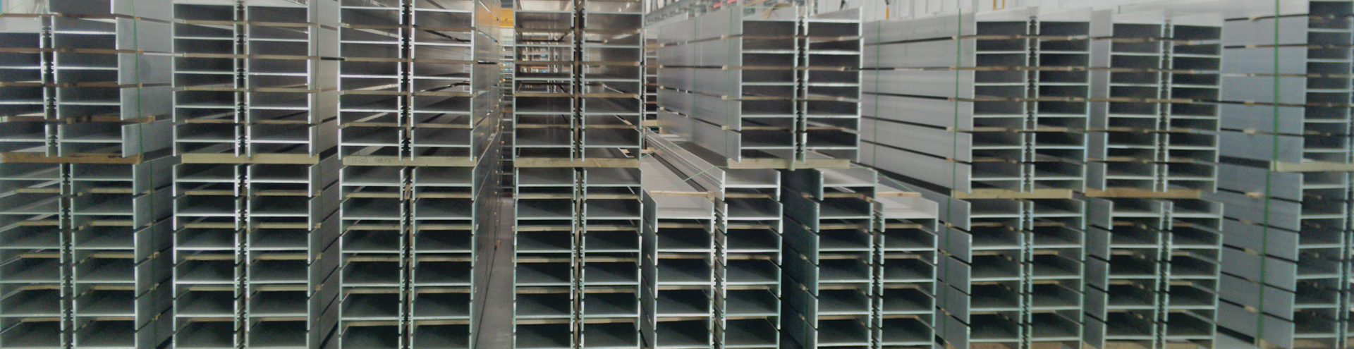
The design of a porthole die for asymmetric hollow extrusion is shown in Figure 1(a). Hollow extruded AA7075 products with complex cross-sections can be used as structural components and represent the industrial case study for current research. The minimum thickness is approximately 3 mm for ribs and 5 mm for the web. A porthole die is required for hollow extrusion, where the male die provides the splitting of the aluminum billet and extrudes the inner contour geometry of the product, and the female die provides the welding chamber and extrudes the outer contour shape of the product. The mandrel of the male die and the die orifice of the female die can be used to regulate the flow of the aluminum melt. Figure 1(b) depicts the schematic configuration of the porthole die used for hollow extrusion, and Figure 1(c) depicts the male die (10) and female die (20), where the former includes portholes (11), bridges (12), welding chamber (13), mandrel (14), and the latter includes the welding chamber cavity (21), orifice (22), and simple support beams (23).
The geometry of the welding chamber cavity is an important design aspect for asymmetric extruded parts. Three different types of cavities (original type, trimmed type, and double-arc type) were designed, as shown in Figures 2(a)-(c). The pocket for the original type is a circle with a diameter of 110 mm. The trimmed type cavity has a cutting plane at a distance of 40 mm from the center point. The double-arc cavity, in addition to the original diameter of 110 mm, has another small arc marked as R. There are two types of die bearing lengths: equal type all 4mm and unequal type 4mm and 12mm. In this study, the welding chamber with the double-arc type pocket was considered, as shown in Figure 2(d). For the current study, the four portholes in the male die have the same cross-section and area. The central axis of the female die orifice coincides with the central axis of the male die mandrel.
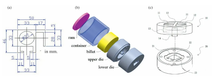
Figure 1. (a) Hollow extruded product with complex profile; (b) Die design for porthole extrusion; (c) Male and female dies.
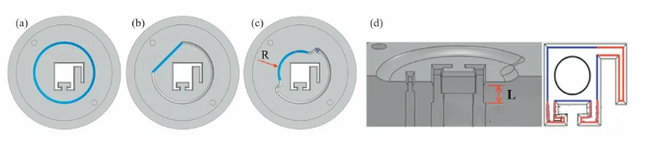
Figure 2. Three different types of welding chamber cavities: (a) original type, (b) trimmed type, and (c) double-arc type; (d) Equal or unequal die bearing lengths.
Finite element analysis of the hollow extrusion process for the three different types of cavity geometries was performed using DEFORM-3D. The simulation conditions were set as follows: billet diameter was 170 mm, billet length was 70 mm, billet temperature was maintained at 480 °C, the constant shear friction coefficient between the die and billet was set to 0.7, and the ram speed was 0.5 mm/s. Among these, the exit product geometry for the shell with the double-arc cavity was more uniform than the other two cases (original and trimmed cavities). Therefore, the double-arc cavity design was adopted for further study. The relationship between ram load and stroke for two different radii (i.e., R40 and 45 mm), where the maximum extrusion loads were 1.19×10⁷ N and 1.21×10⁷ N, respectively. Consequently, the cavity geometry with R40 mm was used for further die design.
By studying the splitting flow of the aluminum billet along the bridge direction during extrusion, particularly at the welding planes, after the aluminum billet flows through the male die and contacts together, the influence of cavity shape and die bearing length was understood. Figure 3(a) depicts the sampled cross-section after the female die chamfer, Figure 3(b) depicts the velocity distribution of the material along the bridge direction, where four marked areas show the four welding planes. Twelve sampling lines were selected to understand the flow state, as shown in Figure 3(c). Labels D – G represent the four billet streams divided by the four portholes in the male die. Labels 1 – 4 indicate the four welding planes. Therefore, D1 indicates the sampling line near welding plane 1, where the material originates from stream D. Each sampling line consists of 300 sampling points. The velocity for each sampling line is the average velocity of the 300 sampling points.
Figure 3. (a) Cross-section for obtaining material flow velocity, (b) Velocity distribution, (c) Twelve sampling lines for calculating flow velocity, where labels D – G represent the four separated billet streams, and labels 1 – 4 represent the four welding planes.
The finite element analysis method is one of the effective problem-solving tools that can enhance product and process performance and significantly reduce the involved cost and time. Besides the cavity profile, several die features influence the extrusion process, namely: the bridge shape of the male die, the recess corner radius, and the chamfer angle of the female die, as shown in Figure 4. The selected design feature parameters are given in Table 1. An experimental layout scheme with 3 factors and 3 levels using an L9 orthogonal array was adopted, and 9 experiments were conducted to study the effects in the simulation, where the output parameters included maximum load, maximum die stress in the male and female dies, aiming for their minimization. The S/N response plots for the smaller-the-better objective and factor contribution histograms are shown in Figures 5-7, for maximum ram load, maximum die stress in the male die, and female die, respectively. From the combination of the orthogonal method and numerical simulation results, it was understood that the factor contributing most to the ram load and male die stress is Factor A (Bridge shape), while the largest contribution to female die stress is Factor B (Chamfer angle).
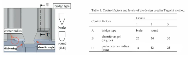
Figure 4. Control factors for die design used in the orthogonal method.
Due to its mandrel characteristics, the male die is manufactured by turning, and further milling due to its porthole characteristics, as shown in Figure 5(a). The female die is manufactured by rough turning and finish milling for the cavity geometry, and wire EDM cutting for the die bearing features, as shown in Figure 5(b). The die material is SKD-61, and a heat treatment operation is performed to achieve a hardness of HRC-48. Figures 5(c)-(d) depict the final product after steady-state extrusion.
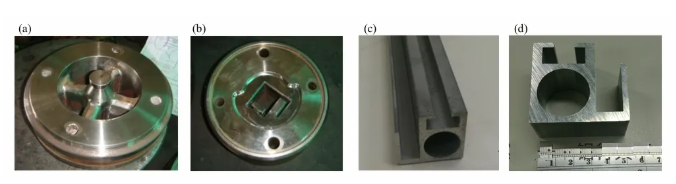
Figure 5. Die Manufacturing: (a) Top view of male die; (b) Top view of female die. (c) Hollow extruded product and (d) Cross-section.
Using the DEFORM-3D finite element analysis software for simulating the welding chamber and bearing design, comparisons were made regarding billet velocity, die stress, and ram load. Three different types of welding chambers (original type, trimmed type, and double-arc type) and two different lengths of die bearings (equal type all 4 mm and unequal type 4 and 12 mm) have been considered for study. Furthermore, we investigated the die stress and ram load for double-arc types of different sizes. The results indicate that the double-arc type provides the best billet flowability and the smallest dead zone, and the ram load shows that R40 mm is smaller than R45 mm. Additionally, unequal bearing lengths lead to better billet flowability.
Post time: Mar-14-2026


